Multi-pipe penetration
You can use this command to create a multi-pipe penetration with a common penetration plate and, optionally, pipe-specific sleeves for pipes passing through a target plate such as a bulkhead or deck. The pipes and penetration plate are prefabricated as a single unit.
Prerequisites
-
If the pipes have flanges, they are added before starting the multi-pipe penetration tool.
-
Plate definition for the penetration plate in the library or project database.
-
Sleeve definition in the library or project database, if using sleeves in the penetration.
-
Penetration settings define clearance values for pipes, sleeves, and flanges.
-
Hull plate material mappings define the material and thickness of the penetration plate based on those of the hull plate.
-
If the hull plate is not created in NAPA or CADMATIC Hull, the target plate's system must have the 'System for hole requests' attribute.
Do the following:
-
Route pipes through the target plate.
-
Select Piping tab > Penetration group > Insert > Multi-pipe penetration.
-
In the Select penetration settings dialog, select the settings to use, and click OK.
-
In the 3D model, select the pipes to include, and press Enter.
-
Select the target plate, and press Enter.
-
You are prompted to specify the plate side. Select Yes to accept the suggested side or No to switch the side.
-
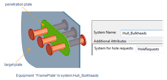
The Create Multi-Pipe Penetration dialog opens, showing information about the target plate, the penetration, and the included pipes.
-
Specify the penetration settings:
Target plate properties
-
Thickness – Displays the thickness of the target plate. When hull plate material mappings are used, the plate part and sleeve part are selected based on the target plate's material. The penetration plate thickness matches the target plate thickness; if an exact match is unavailable, the next greater thickness is selected.
Penetration properties
-
Description – Displays the material selected for the penetration plate. When hull plate material mappings are used, the material is chosen automatically. Click Change to change it.
Note: It is recommended to select a plate of same thickness as the target plate.
-
System – Displays the system for the penetration. Click Change to change it.
Penetration parameters
-
Shape – Select a shape that fits the number and position of included pipes: bicycle chain, oval, round, rounded rectangle, or triangle. You can use the Rotate tool to affect the shape of the plate, which might be helpful when the pipes are not aligned. The corners of a rounded rectangle or triangle can be rounded by the intersecting part with the greatest target hole radius. Rotation cannot be undone.
-
Overlap – Displays the amount of overlap between the penetration plate and the target plate. Click Move to move the penetration plate. You are prompted to define a reference point and its new location. This action does not affect the shape. Moving cannot be undone.
Penetration group parameters
- Main pipeline – If Main pipeline is selected automatically is selected, the pipe with the largest Nominal Size determines the penetration's main pipeline. Clear the option to select the main pipeline manually. You can change this later with the Main pipeline of multi-pipe penetration command.
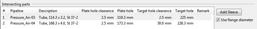
Intersecting parts displays the included pipes. For each part, select whether the dimensions for hole and plate overlap are taken from the flange. If the option is not available, the dimensions are taken from the pipe or sleeve. The measures come automatically for each nominal size from the selected penetration settings.
Select a pipe to highlight it in work views and access its options:
-
Use flange diameter – If the pipe has flanges, this option is selected by default to calculate sleeve size from flange diameter. Clear the option to calculate sleeve size from pipe diameter.
-
-
Click OK to create the penetration.
-
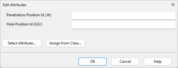
In the Edit Attributes dialog, specify attribute values for the hole request, and click OK.
-
To submit a hole request to hull designers, open the Hole Manager and select Send Request.
Tip: If needing to change the shape of the penetration plate or hole request, it is easiest to delete the multi-pipe penetration and create a new one. Plates can also be edited manually via Structural tab > Plate group > Edit.